Calico Research
Calico creates and manages a flat layer 3 network, assigning each workload a fully routable IP address.
官网:https://www.projectcalico.org/
网络演进
为什会有 calico 的出现 ?
它解决了什么问题 ? 和其它网络方案又有什么区别 ?
开篇即提到 calico 是一个去掉网络虚拟化的纯三层路由网络解决方案,我想有必要对网络虚拟化和网络功能虚拟化(NFV)这两个概念做一个强调。
网络虚拟化:
网络虚拟化最基础的技术莫过于分层,要实现分层有两种手段,一个是映射,另一种就是封装。- 映射:主要思路是转发时替换报文语义,如何替换将需要设备进行查询。
eg:端口映射、静态映射、PAT等NAT技术。 - 封装:把需要的报文语义添加到网包中,处理的时候一层层的解封装即可,尽量对设备透明。
eg:隧道技术、vlan等
- 映射:主要思路是转发时替换报文语义,如何替换将需要设备进行查询。
网络功能虚拟化
通过使用x86等通用性硬件以及虚拟化技术,来承载很多功能的软件处理。通俗点说,就是将承载数据传输的一系列网元,使用虚拟化的方式实现,比如 Linux bridge、veth pair、vRouter 等等。
如下图所示,阐述了两套网络解决方案的不同之处。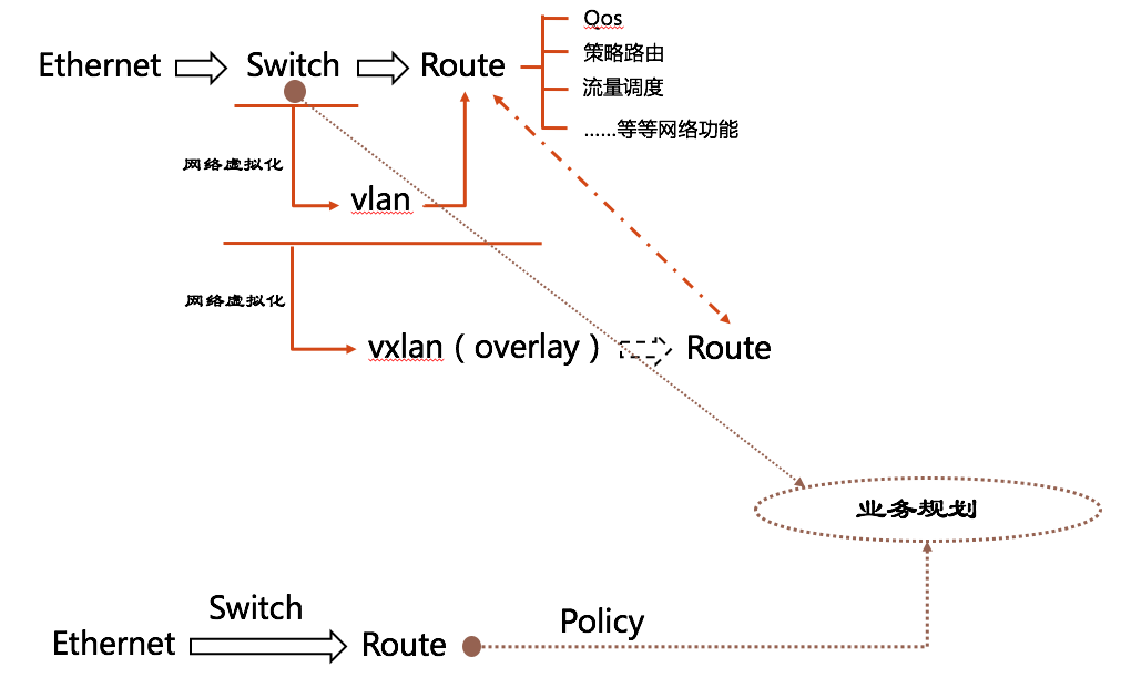
想象一下,我们现在有几台PC需要组网,怎么办?直接找个交换机来。大家网线一插,就是个局域网了。现在我们中间有个人与我们业务不同,需要进行网络隔离,这就有了 Vlan。当然,例子举得有点粗暴,真实业务场景没有这么简单。总之,由于业务网络规划等原因,有了一个比较复杂的二层网络。
到了我们云计算场景中呢,有了一个 Vxlan 这样的技术,在三层网络中建立二层隧道,有了 overlay 网络这个概念,你 underlay 网络爱咋样咋样,我自行构建一个二层网络,再进行租户隔离。另外,留给Vxlan 的比特位也远远多于 Vlan,可以支持更多的租户。
那么,Calico 去掉了分层和二层组网(并不是没了),形成的这个平面的三层网络如何解决业务规划等问题呢?答案就是 policy!它使用 route 加上 policy 将 network 又抽象了一层,后面我们再进行详细的说明。
另外,SDN 在这样的网络演进中又充当了一个什么角色呢?
- SDN & SD-WAN
- OpenFlow VS Segment Routing
在我看来,虽然openflow系的解决方案在 overlay 网络中如鱼得水,但让控制器给那些看起来很初级的网络协议栈背锅,也是有些滑稽的。所以,我更看好 segment routing 这种集中控制加上分布式智能的模式。关于 SDN 这部分内容以后有机会了再跟大家分享讨论。
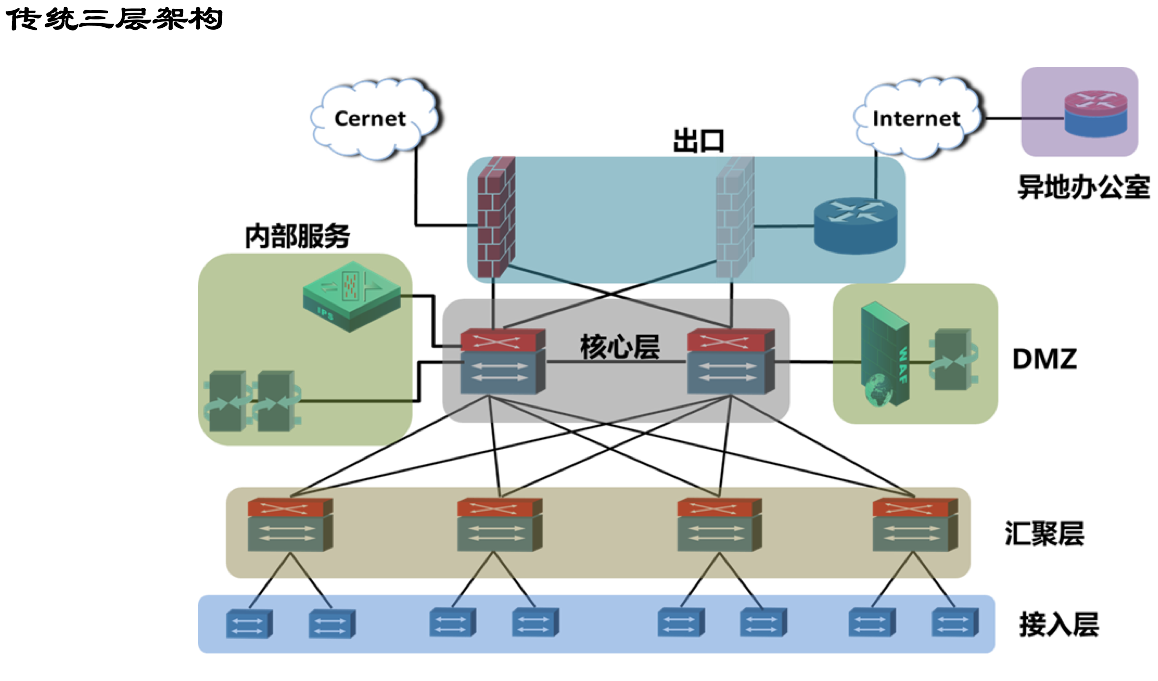
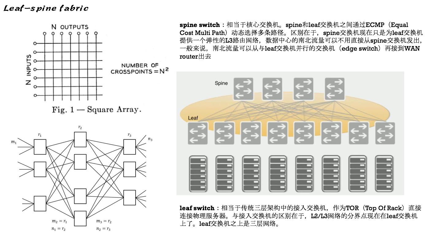
By the way,关于网络的演进,有必要了解一下传统三层网络和叶脊网络,下面就先直接丢两张图,混个脸熟。
科普推荐:https://zhuanlan.zhihu.com/p/29975418
Calico网络设计
How it works?
这是官网的介绍图: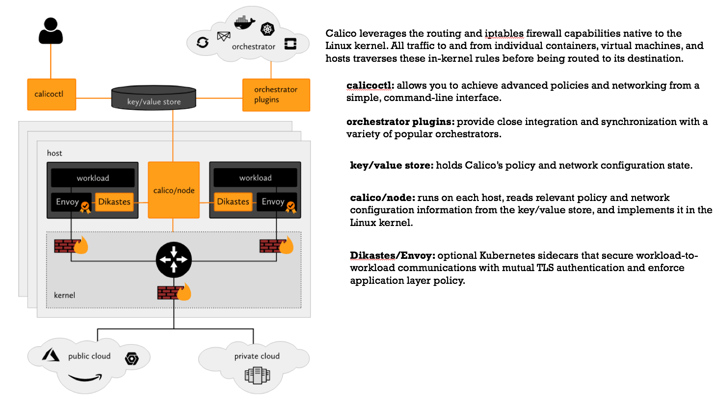
很清楚的说明了各个组件的功能和如何进行协同工作,下面我们还是把重心放在网络实现上。
Similarly,一张图足以说明: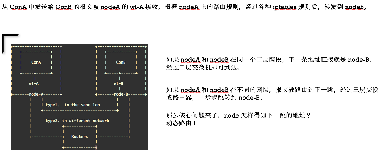
PS:其实第一种情况控制层面可以直接获得下一跳地址,但还是直接使用了路由协议。
首先我们来看看节点在同一个广播域的情况,官网原图—— Calico Over Ethernet Fabrics: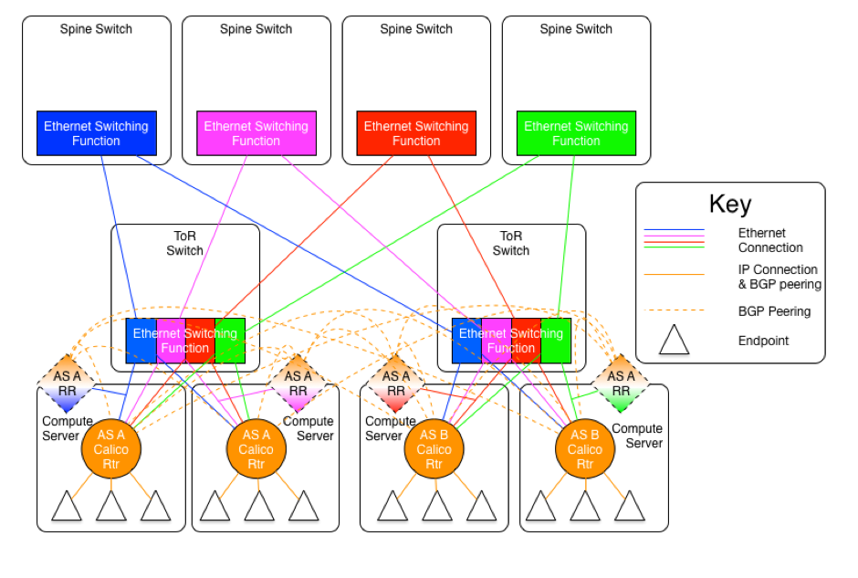
二层为什么要这样设计呢?请参见前面关于 fabric 结构的科普链接和官网的设计说明。
下面我们将四个广播域减少成两个,且暂时忽略 AS 和 RR 的概念,那么可以直接将逻辑抽象出这张图: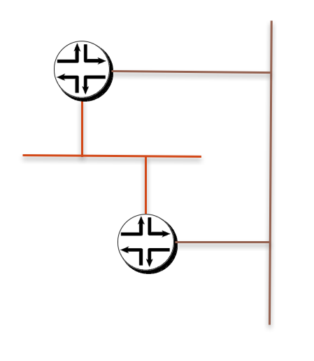
路由器就是两台 calico node,上面创建的直连网络通过 ECMP 传输。
接着我们看看实现细节: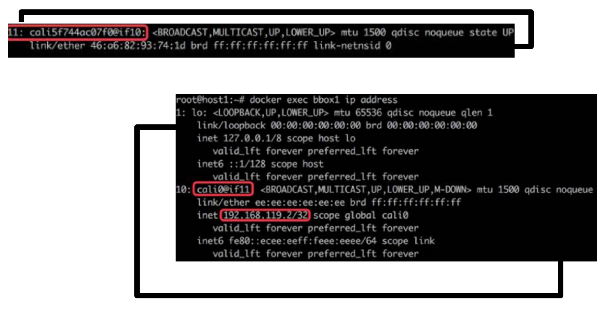
首先有一对 tap 接口,socket 获得的数据是共享的,嗯……可能不太准确,就先理解成把数据传给一端,也就相当于传给了另一端^_^……它们分别位于宿主机(calico node)和 workload(container or namespace)。
接着,是路由收敛和策略制定: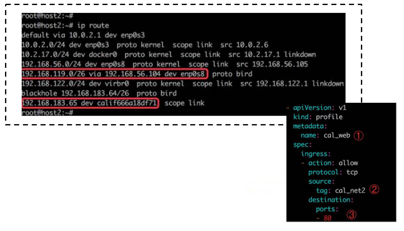
目的是存在于本地的 container 的地址,直接往对应的接口扔,跨节点就扔给下一跳(通过 BGP 路由学习到的,该协议由 bird 软件支持);创建网络时给各个前缀打上了标签,可以自由制定策略(底层由 iptables 支持),默认 deny。
说到这里,calico 的基本原理其实就已经阐述清楚了,剩下的就是怎么与物理网络融合,进行路由条目学习的事情了。Calico 选择了 BGP 进行路由收敛,下节我们就把 calico 官网推荐的几种架构就行简单介绍。
在此之前,可能需要对一下内容有一定的了解:
- AS(自治系统)
- IGP(内部网关协议)
- 距离矢量:rip
- 链路状态:ospf、is-is
- 混合型:eigrp
- EGP(外部网关协议)
- BGP:ibgp 与 ebgp
- BGP 科普推荐:https://zhuanlan.zhihu.com/p/25433049
- calico 选择 BGP 的原因:https://www.projectcalico.org/why-bgp/
BGP设计
Since Calico is, itself, a routed infrastructure, there are more engineering, architecture, and operations considerations thathave to be weighed when running Calico with an IP routed interconnection fabric.
在 BGP 设计中一般有如下三种架构,需要注意的是,比如 EBGP 架构,并不代表其不使用 iBGP。
- IBGP
- EBGP
- IBGP/EBGP
公认比较废的是 IBPG 架构,比较好的是 IBGP/EBGP,但俗话说,没有最好的,只有更适合的,在 calico 形成的拓扑结构中,EBGP 架构是最合适的。
根据场景应用,官方给出了五种网络设计:
https://docs.projectcalico.org/v3.3/reference/private-cloud/l3-interconnect-fabric
The AS Per Rack model
即以 leaf 节点(或者说 ToR) 及其所连接的 calico node 为一个自治域(AS)。那么,spine 节点是提供二层连接的 ethernet,还是加入三层路由并设计为单独的自治域,这又分成了两种情况。
开始官网搬砖:
This model is the closest to the model suggested by IETF RFC 7938.
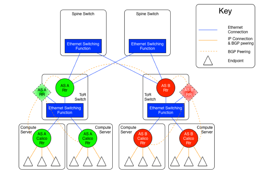
As mentioned earlier, there are two versions of this model, one with an set of Ethernet planes interconnecting the ToR switches, and the other where the core planes are also routers. The following diagrams may be useful for the discussion.
The diagram above shows the AS per rack model where the ToR switches are physically meshed via a set of Ethernet switching planes.
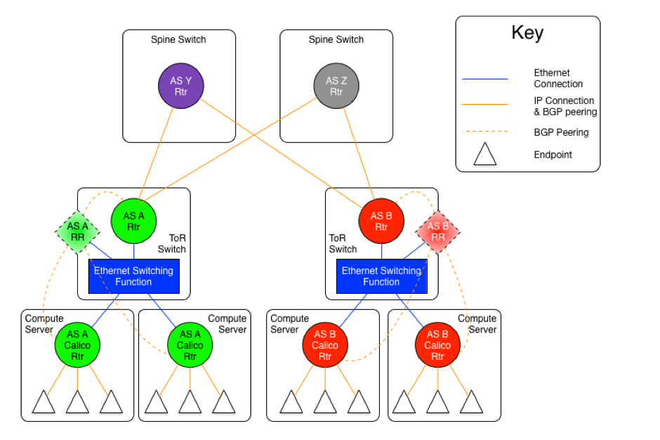
The diagram above shows the AS per rack model where the ToR switches are physically meshed via a set of discrete BGP spine routers, each in their own AS.
In this approach, every ToR-ToR or ToR-Spine (in the case of an AS per spine) link is an eBGP peering which means that there is no route-reflection possible (using standard BGP route reflectors) north of the ToR switches.
If the L2 spine option is used, the result of this is that each ToR must either peer with every other ToR switch in the cluster (which could be hundreds of peers).
If the AS per spine option is used, then each ToR only has to peer with each spine (there are usually somewhere between two and sixteen spine switches in a pod). However, the spine switches must peer with all ToR switches (again, that would be hundreds, but most spine switches have more control plane capacity than the average ToR, so this might be more scalable in many circumstances).
Within the rack, the configuration is the same for both variants, and is somewhat different than the configuration north of the ToR.
Every router within the rack, which, in the case of Calico is every compute server, shares the same AS as the ToR that they are connected to. That connection is in the form of an Ethernet switching layer. Each router in the rack must be directly connected to enable the AS to remain contiguous. The ToR’s router function is then connected to that Ethernet switching layer as well. The actual configuration of this is dependent on the ToR in use, but usually it means that the ports that are connected to the compute servers are treated as subnet or segment ports, and then the ToR’s router function has a single interface into that subnet.
This configuration allows each compute server to connect to each other compute server in the rack without going through the ToR router, but it will, of course, go through the ToR switching function. The compute servers and the ToR router could all be directly meshed, or a route reflector could be used within the rack, either hosted on the ToR itself, or as a virtual function hosted on one or more compute servers within the rack.
The ToR, as the eBGP router redistributes all of the routes from other ToRs as well as routes external to the data center to the compute servers that are in its AS, and announces all of the routes from within the AS (rack) to the other ToRs and the larger world. This means that each compute server will see the ToR as the next hop for all external routes, and the individual compute servers are the next hop for all routes internal to the rack.
我将这两种情况的逻辑抽出来展现一下。
第一种: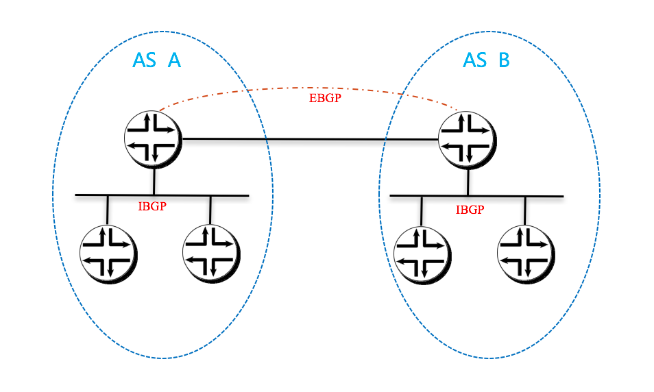
第二种: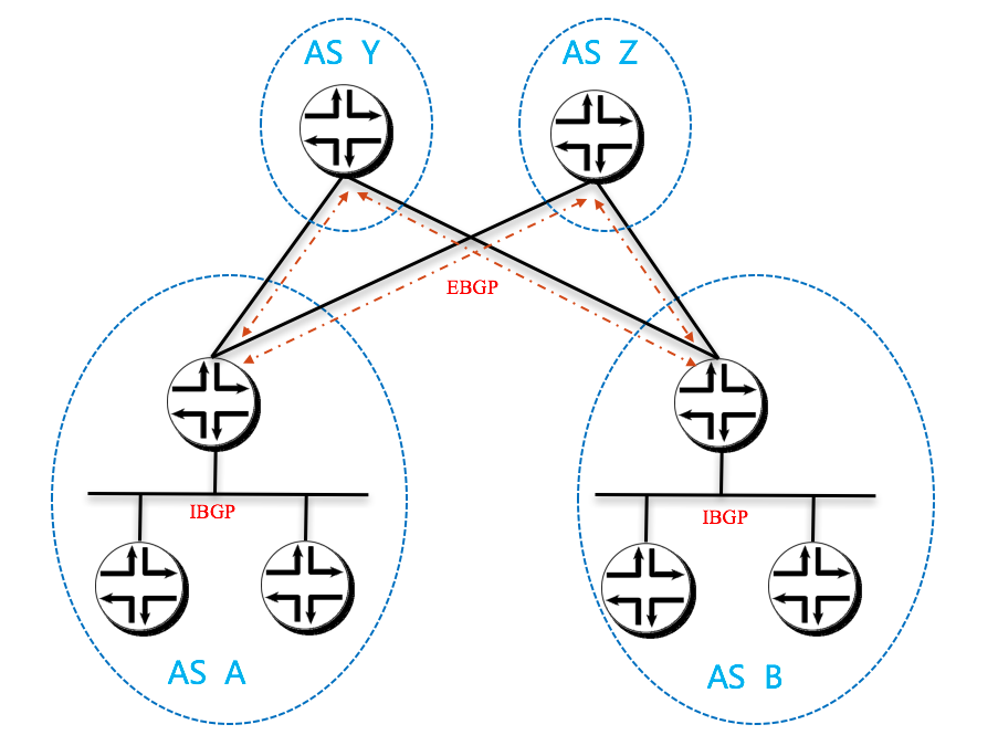
The AS per Compute Server model
即以每个 calico node 和 leaf node 分别设计为一个 AS。同样,spine 节点是提供二层连接的 ethernet,还是加入三层路由并设计为单独的自治域,这又分成了两种情况。
继续官网搬砖:
This model takes the concept of an AS per rack to its logical conclusion. In the earlier referenced IETF RFC 7938 the assumption in the overall model is that the ToR is first tier aggregating and routing element. In Calico, the ToR, if it is an L3 router, is actually the second tier. Remember, in Calico, the compute server is always the first/last router for an endpoint, and is also the first/last point of aggregation.
Therefore, if we follow the architecture of the draft, the compute server, not the ToR should be the AS boundary. The differences can be seen in the following two diagrams.
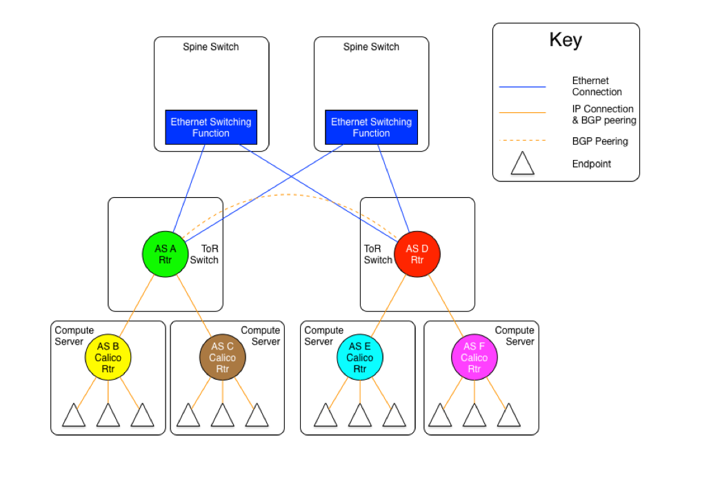
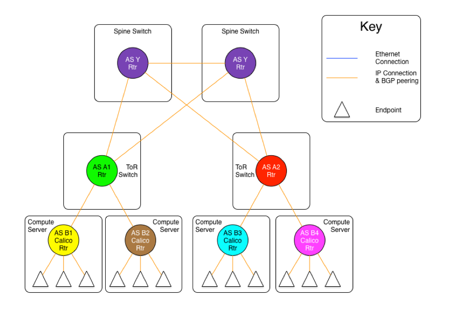
The diagram above shows the AS per compute server model where the ToR switches are physically meshed via a set of Ethernet switching planes.
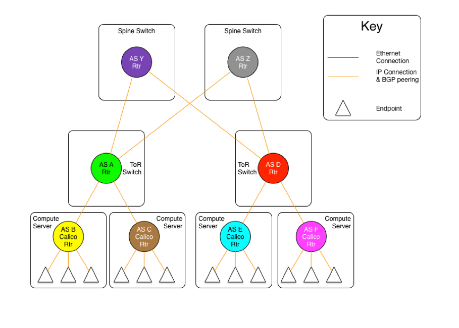
The diagram above shows the AS per compute server model where the ToR switches are physically connected to a set of independent routing planes.
As can be seen in these diagrams, there are still the same two variants as in the AS per rack model, one where the spine switches provide a set of independent Ethernet planes to interconnect the ToR switches, and the other where that is done by a set of independent routers.
The real difference in this model, is that the compute servers as well as the ToR switches are all independent autonomous systems. To make this work at scale, the use of four byte AS numbers as discussed in RFC 4893. Without using four byte AS numbering, the total number of ToRs and compute servers in a Calico fabric would be limited to the approximately five thousand available private AS 5 numbers. If four byte AS numbers are used, there are approximately ninety-two million private AS numbers available. This should be sufficient for any given Calico fabric.
The other difference in this model vs. the AS per rack model, is that there are no route reflectors used, as all BGP peerings are eBGP. In this case, each compute server in a given rack peers with its ToR switch which is also acting as an eBGP router. For two servers within the same rack to communicate, they will be routed through the ToR. Therefore, each server will have one peering to each ToR it is connected to, and each ToR will have a peering with each compute server that it is connected to (normally, all the compute servers in the rack).
The inter-ToR connectivity considerations are the same in scale and scope as in the AS per rack model.
同样,我将这两种情况的逻辑抽出来展现一下。
第一种: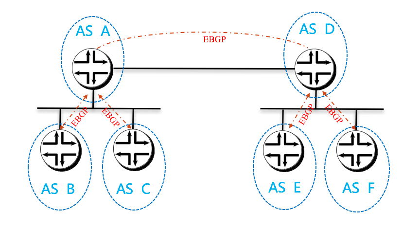
第二种: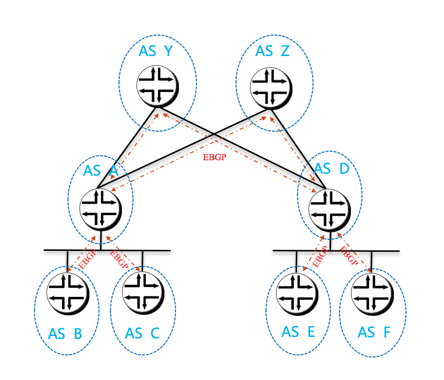
The Downward Default model
再强调一遍,合适的才是好的嘛!
该方案就加入了更多 calico 的本地特色。
搬砖:
The final model is a bit different. Whereas, in the previous models, all of the routers in the infrastructure carry full routing tables, and leave their AS paths intact, this model 6 removes the AS numbers at each stage of the routing path. This is to prevent routes from other nodes in the network from not being installed due to it coming from the local AS (since they share the source and dest of the route share the same AS).
The following diagram will show the AS relationships in this model.
In the diagram above, we are showing that all Calico nodes share the same AS number, as do all ToR switches. However, those ASs are different (A1 is not the same network as A2, even though the both share the same AS number A ).
While the use of a single AS for all ToR switches, and another for all compute servers simplifies deployment (standardized configuration), the real benefit comes in the offloading of the routing tables in the ToR switches.
In this model, each router announces all of its routes to its upstream peer (the Calico routers to their ToR, the ToRs to the spine switches). However, in return, the upstream router only announces a default route. In this case, a given Calico router only has routes for the endpoints that are locally hosted on it, as well as the default from the ToR. Since the ToR is the only route for the Calico network the rest of the network, this matches reality. The same happens between the ToR switches and the spine. This means that the ToR only has to install the routes that are for endpoints that are hosted on its downstream Calico nodes. Even if we were to host 200 endpoints per Calico node, and stuff 80 Calico nodes in each rack, that would still limit the routing table on the ToR to a maximum of 16,000 entries (well within the capabilities of even the most modest of switches).
Since the default is originated by the Spine (originally) there is no chance for a downward announced route to originate from the recipient’s AS, preventing the AS puddling problem.
There is one (minor) drawback to this model, in that all traffic that is destined for an invalid destination (the destination IP does not exist) will be forwarded to the spine switches before they are dropped.
It should also be noted that the spine switches do need to carry all of the Calico network routes, just as they do in the routed spines in the previous examples. In short, this model imposes no more load on the spines than they already would have, and substantially reduces the amount of routing table space used on the ToR switches. It also reduces the number of routes in the Calico nodes, but, as we have discussed before, that is not a concern in most deployments as the amount of memory consumed by a full routing table in Calico is a fraction of the total memory available on a modern compute server.
逻辑抽象一下: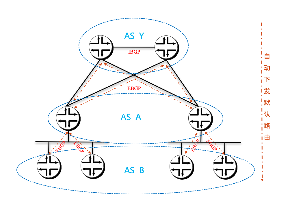
Recommendation
搬砖:
The Project Calico team recommends the use of the AS per rack model if the resultant routing table size can be accommodated by the ToR and spine switches, remembering to account for projected growth.
If there is concern about the route table size in the ToR switches, the team recommends the Downward Default model.
If there are concerns about both the spine and ToR switch route table capacity, or there is a desire to run a very simple L2 fabric to connect the Calico nodes, then the user should consider the Ethernet fabric as detailed.
If a Calico user is interested in the AS per compute server, the Project Calico team would be very interested in discussing the deployment of that model.
概念补充介绍
- Full-mesh
- Router Reflector
Internet接口设计
This is a problem that can not be ignored.
We must know what we need !
- 默认路由
- 默认路由 + 部分路由
- 完全的Internet路由表
Options:
- 单宿主末端网络
- 多宿主末端网络(单ISP单边界,单ISP多边界)
- 标准多宿主网络